This guide explains what you will be able to look up when an oxygen-sensor signal does not make sense: normal voltage ranges, warm-up behavior, upstream versus downstream sensors, testing methods, and common diagnostic mistakes. O2 sensor voltage readings are useful, but only when you know whether the vehicle uses a conventional narrowband sensor or a wideband air-fuel sensor. Here's the chemistry, here's the spec, here's what to do with it.
What the oxygen sensor is actually measuring
A conventional zirconia oxygen sensor does not work like a simple fuel-quality meter. It compares oxygen content in the exhaust with oxygen in the outside reference air. Once the sensing element reaches operating temperature, the voltage changes sharply around the stoichiometric air-fuel ratio. For gasoline, that point is close to 14.7 parts air to one part fuel, although the exact target depends on engine calibration and fuel composition.
A low signal, often near 0.1 to 0.2 volts, generally indicates a lean exhaust condition with more oxygen present. A high signal, commonly near 0.8 to 0.9 volts, generally indicates a rich condition. That interpretation applies most directly to a heated, narrowband zirconia sensor. It does not mean that every low voltage proves a vacuum leak or that every high voltage proves a leaking injector.
Reference Box: A narrowband zirconia sensor switches rapidly around stoichiometric operation; it is best at showing mixture correction, not measuring an exact air-fuel ratio.
Before testing, identify the sensor location and circuit. Sensor 1 is normally ahead of the catalytic converter, while Sensor 2 is normally behind it. Bank 1 contains the cylinder with number one. A V6 or V8 can have Bank 2, so a code such as P0136 is more useful when paired with the vehicle wiring diagram and live data description.
Normal O2 sensor voltage readings on a warm engine
A cold sensor may sit near zero volts, and that is not automatically a failure. The powertrain control module often ignores the signal until the heater brings the element to operating temperature. Depending on the design, closed-loop operation may begin after several seconds or after a longer period of idling and driving.
Once warm, a conventional upstream sensor should usually switch between roughly 0.1 and 0.9 volts. On a functioning system in closed loop, the transitions can occur several times per second at a steady warm idle. The exact speed changes with engine load, fuel strategy, sensor design, and scan-tool sampling rate. A digital multimeter may display a slower or less complete pattern than a scope or professional scan tool.
At 2,500 rpm with no load, the signal should normally continue to move rather than remain fixed. A sensor that stays near 0.45 volts can be biased, disconnected, or displayed incorrectly by the test equipment. Some scan tools show a calculated value rather than the raw sensor voltage, so compare the data label with the service information before drawing a conclusion.
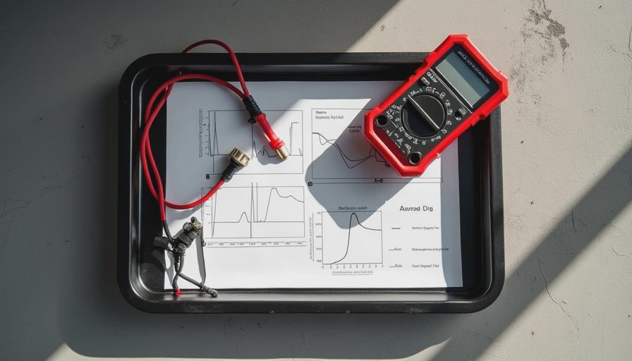
How to test the signal without damaging the circuit
Start with a visual inspection. Look for melted wiring near the exhaust, water intrusion in the connector, loose grounds, and aftermarket splices. Exhaust leaks ahead of the sensor can draw outside air into the pipe and create a false lean signal. A contaminated connector can also produce an intermittent reading that looks like a failing sensor.
Back-probe the signal circuit only when the manufacturer permits that method. Do not pierce insulation unnecessarily, and never short the signal wire to a heater-power wire. Use a high-impedance meter, preferably with a graphing function, and keep the vehicle securely supported if testing requires access underneath. Exhaust components become extremely hot, so wear eye protection and keep wiring, clothing, and hands away from the pipe and converter.
With the engine fully warm, observe the signal at idle and during a controlled increase in engine speed. A brief propane enrichment test should drive a conventional sensor high, while a carefully created lean condition should drive it low. Follow the service manual procedure; an uncontrolled fuel or air test creates fire and drivability risks. Do not spray flammable cleaner around a hot exhaust system.
Interpreting upstream and downstream signals
The upstream sensor helps the module adjust fuel delivery. Its O2 sensor voltage readings normally change often because the control system deliberately moves slightly rich and lean to keep the converter supplied with the right exhaust mixture. A healthy upstream pattern is active, not necessarily smooth.
The downstream sensor monitors oxygen after the catalytic converter. Its voltage can vary, but it generally should be steadier than the upstream signal once the converter is hot. Depending on the vehicle, a warm downstream reading may sit around 0.6 to 0.8 volts, but there is no universal fixed value. A downstream waveform that closely copies the upstream waveform can support a catalyst-efficiency concern, yet wiring faults, exhaust leaks, and temperature problems must be ruled out first.
A catalyst code does not automatically mean the oxygen sensor is defective. Replacing Sensor 2 without checking misfire history, fuel trims, exhaust leaks, and converter temperature can waste several hundred dollars. Read the complete code description and freeze-frame data before ordering parts.
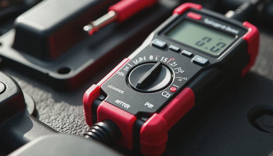
Wideband sensors require a different approach
Many newer engines use wideband air-fuel sensors instead of traditional switching sensors. These devices can report mixture conditions over a broader range, but their signal may be a pump-current value, a biased voltage, or a manufacturer-specific calculated air-fuel ratio. A reading of 0.45 volts on a scan tool does not necessarily carry the same meaning as 0.45 volts from a conventional narrowband sensor.
For wideband diagnosis, use the factory wiring diagram and scan-tool data list. Check the heater circuit, reference voltage, pump-current signal, and air-fuel equivalence ratio when those parameters are available. Generic parts-store interpretations can be misleading because some tools label a wideband value as O2 voltage even though the computer is reporting a processed signal.
This distinction is especially important when comparing O2 sensor voltage readings across different model years. The connector may look similar while the control strategy is entirely different. Never substitute a universal sensor solely because the thread size and wire count match.
Common causes of abnormal readings
A low, slow, or fixed signal can result from a vacuum leak, unmetered air, low fuel pressure, restricted injector, exhaust leak, damaged signal wire, poor heater operation, or a sensor that has aged from contamination. Silicone sealants, coolant, oil ash, and certain fuel additives can damage the sensing element. A rich, fixed-high signal can come from excessive fuel pressure, a leaking injector, restricted air intake, or a shorted circuit rather than the sensor itself.
Fuel-trim data helps separate these possibilities. Positive long-term fuel trim means the computer is adding fuel to correct a lean condition; negative trim means it is removing fuel to correct a rich condition. Compare both banks when possible. If both banks show similar positive trim, suspect a shared issue such as low fuel pressure or unmetered air. If one bank is different, inspect that bank's intake, exhaust, injector, and sensor wiring.
A practical diagnostic sequence
Record the trouble codes and freeze-frame conditions first. Confirm engine temperature, inspect the wiring, and verify that the sensor heater receives the correct power and ground. Warm the engine completely, then watch the signal at idle and at a steady elevated speed. Compare upstream and downstream behavior, review short- and long-term fuel trim, and test for exhaust leaks before condemning a component.
If the signal responds correctly to rich and lean changes but a code remains, investigate the circuit, catalyst, and control strategy. If it never responds, verify the test method and power supply before replacing the sensor. Parts-counter staff can save a customer from an unnecessary repair by asking whether the reading is raw voltage, calculated data, or wideband current.
Used sensors and contaminated cleaning materials belong in accordance with local automotive-waste rules; do not burn, crush, or place removed electronic parts in a fluid drain. If your customer asks, the one-line answer is this: O2 sensor voltage readings are evidence, not a verdict. Combine the signal pattern with temperature, fuel trims, circuit tests, and the vehicle's service information for a sound diagnosis.

No comments yet — be the first to share a thought.