If you work on modern cars, you have probably pulled up a fault code and found yourself hunting for a module that talks over a single wire. That wire is a LIN bus, and the lin bus voltage you measure tells you exactly what the network is doing. This guide covers the basics of the bus, normal voltage levels and waveforms, a step-by-step test procedure, and the most common faults you will see on the service floor. Read it once, and you will be able to field the next "why won't my window switch work" question without dropping into a 30-minute diagnostic session.
What Is LIN Bus and Why Does Voltage Matter?
LIN stands for Local Interconnect Network. It is a single-wire, master-slave serial bus used for low-speed commands and sensor data. The master node, usually a body control module, schedules traffic and sends a break snippet to wake the slaves. Each slave node listens for its own identifier and either acknowledges or acts. The wire is pulled up to battery voltage through resistors on both the master and the slaves. When nothing is being sent, the bus idles high. When a node wants to send a dominant bit, it shorts the wire to ground through its transistor. The transition from high to low and back is the voltage signal the modules decode. Understanding this high/low pattern is the entire game of lin bus voltage troubleshooting.
Normal Lin Bus Voltage Values and Waveform
A healthy bus has two clear states. Idle (recessive) voltage tracks the battery: about 12.0 to 12.6 V with the engine off, 13.8 to 14.4 V with the engine running. A dominant bit pulls the wire to less than 1 V, though you may see a slight offset depending on the ground quality.

The receiver decides between 0 and 1 using thresholds based on the module's supply voltage: anything above 0.6 x Vbat is recessive, anything below 0.4 x Vbat is dominant. On a nominal 12 V supply, the switching window is about 4.8 to 7.2 V. A lin bus voltage reading inside that dead zone means the signal is neither a solid 1 nor a solid 0, and the module may interpret random bits. On a scope, a healthy frame looks like a series of square pulses with sharp edges. The bit time at the maximum 20 kbit/s is 50 microseconds, so a 2 ms per division sweep shows several full frames.
How to Test Lin Bus Voltage Without Guessing
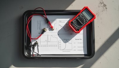
Start with a digital multimeter set to DC volts. Measure from the LIN bus pin to chassis ground with the module powered. The reading should stay near battery voltage. If it comes back 0 V, someone has shorted the wire to ground or a slave is holding the bus down. If it reads battery voltage with no pulses, the master may be dead or asleep. But a meter cannot show you the digital traffic. You need an oscilloscope to see the actual frames. Set the probe to 5 V per division and the time base to 2 ms per division, then trigger on a falling edge. You should see a wake-up pulse followed by a break field, a sync field, and the data payload. If the top of the waveform is higher than battery voltage, you have an open ground or a miswired pull-up. If the bottom rises more than 1 V above ground, you have a high-resistance ground in the slave, not in the wire.

Common Faults and the Voltage Clues They Leave Behind
The bus can fail in a few predictable ways. A short to ground is common after a harness rub or water intrusion in a connector. It locks the lin bus voltage to 0 V, and every node on that segment stops communicating. A short to battery locks the bus at 12 V or higher, and the master logs a circuit range fault because it cannot pull the wire low. An open wire causes the bus to float, typically showing a few tenths of a volt because of module input capacitance. Slow edges on the waveform point to extra capacitance or a marginal ground. A dead slave transceiver may hold the bus permanently low even while the module itself looks fine on the bench. The procedure to isolate a bad node is the same every time: watch the scope while disconnecting each slave one at a time. The moment the waveform snaps back to square, you have found the part that is loading the bus.
Reference Box: Lin Bus Voltage Specs at a Glance
The numbers you need for the service write-up: idle bus voltage equals battery voltage, dominant bits sit below 0.4 x Vbat, and recessive bits sit above 0.6 x Vbat. On a 12 V system, the transition zone is roughly 4.8 to 7.2 V. The bus runs at up to 20 kbit/s, and the standard that governs the physical layer is ISO 17987. The master's pull-up resistor is about 1 kΩ with a series diode; each slave adds a 30 kΩ pull-up. When a customer asks what voltage a LIN bus runs at, the answer is "battery voltage" in the idle state and "near ground" when sending a dominant bit. That is the entire one-line explanation.
Five Steps to Isolate a Bus Fault
Use this sequence when the wiring and connectors look normal. First, confirm the module supply voltage is in range. Second, measure the bus idle voltage with the master powered. Third, set up an oscilloscope and verify you have a start frame. Fourth, disconnect each slave node one at a time while watching the waveform. Fifth, replace the node that restores a clean square wave. If you work through these steps in order, you will solve most LIN communication faults without replacing a single module by guesswork.


No comments yet — be the first to share a thought.