If a customer comes in with a check engine light, poor fuel economy, or a rough idle, the mass air flow (MAF) sensor is often the first component you should suspect. Knowing how to perform a proper MAF sensor mass air flow sensor testing procedure can save hours of diagnostic time. In this guide, I’ll walk through the tools you need, the step-by-step process, and how to interpret the results so you can get that vehicle back on the road with confidence.
Before we dive into the testing, let’s talk about what the MAF sensor actually does. It measures the volume and density of air entering the engine and sends that data to the ECU. The ECU uses this information to calculate the correct fuel injection quantity. If the sensor is contaminated or failing, the air/fuel ratio goes off, and driveability suffers. Most MAF sensors are either hot-wire or hot-film type, and they typically output a frequency or voltage signal. The key specs are usually in the service manual, but the general voltage range for a healthy sensor at idle is around 0.5 to 1.5 volts (on a 0-5V scale), and at wide-open throttle it can go up to 4.5-5V.
Why Testing the MAF Sensor Matters
Jumping straight to replacement without testing is a common mistake. A dirty MAF sensor can mimic the symptoms of a bad one, but a thorough cleaning may restore it. MAF sensor mass air flow sensor testing lets you differentiate between a sensor that needs cleaning and one that needs replacement. It also helps you verify that the wiring and the ECU are communicating properly. On many modern vehicles, a failing MAF will set a code like P0100, P0101, P0102, or P0103, but sometimes the code is for a related component, like the oxygen sensor. Testing the MAF first eliminates a major unknown.
Reference Box: The typical failure modes for a MAF sensor are contamination (oil, dirt, debris) and electronic failure (open circuit, short, drift). Cleaning only addresses contamination. If the output voltage is out of spec even after cleaning, the sensor is likely bad.
Tools You Need for MAF Sensor Mass Air Flow Sensor Testing
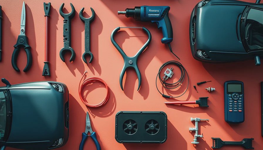
You don’t need a huge arsenal. Here’s what I recommend having on hand:
- A digital multimeter (DMM) with frequency measurement capability (most modern DMMs have it).
- A scan tool capable of reading live data and MAF sensor grams per second (g/s) or voltage.
- A set of back-probing pins or a breakout box to access the sensor connector without piercing the wires.
- The factory service manual for the specific vehicle, or access to a repair database like ALLDATA or Mitchell1.
- MAF sensor cleaner (specialized aerosol, not brake cleaner or carb cleaner).
- Safety glasses and nitrile gloves.
Some technicians prefer to test the sensor on the vehicle using a graphing multimeter to see the waveform, but a DMM and scan tool are enough for a pass/fail test.
Step-by-Step Procedure for MAF Sensor Mass Air Flow Sensor Testing
Here’s the procedure I teach my students. Always start with the engine off and the key removed.
- Visual inspection. Check the connector for corrosion, bent pins, or damaged wires. Look at the air filter and intake duct for leaks or restrictions. A torn intake boot after the MAF can introduce unmetered air and cause a false lean condition.
- Check for power and ground. Set your DMM to DC volts. Back-probe the sensor connector and turn the key to ON (engine off). You should have battery voltage (12.6V) on the power pin and a good ground (less than 0.1V drop to battery negative). If power is missing, trace the circuit back to the fuse or relay.
- Test the signal output at idle. Start the engine and let it idle. Using your DMM on DC volts, back-probe the signal wire (usually the middle pin). A healthy hot-wire MAF will read around 0.5 to 1.5V at idle, depending on the model. Alternatively, use the scan tool to read the MAF sensor grams per second. Idle values typically range from 2 to 7 g/s for a small 4-cylinder engine, and up to 15 g/s for a large V8.
- Test the signal output at wide-open throttle. Rev the engine to about 3000-4000 RPM (or have an assistant hold it). The voltage should rise smoothly to near 5V (or the g/s value should increase proportionally). A sudden jump or no response indicates a failing sensor.
- Frequency test (if applicable). Some MAF sensors output a frequency signal instead of voltage. Switch your DMM to frequency mode. At idle, you might see around 100-250 Hz, increasing to 800-1200 Hz at WOT. Check the service manual for exact specs.
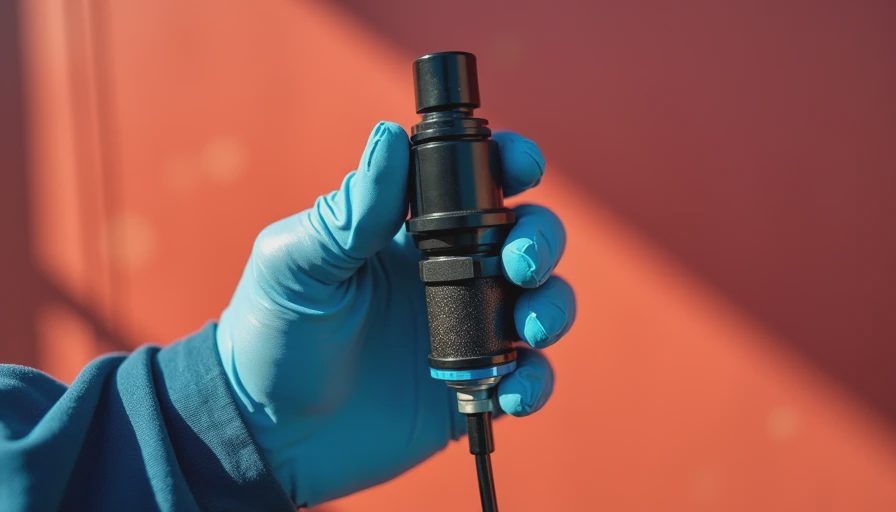
- Clean the sensor if readings are slightly off. Remove the sensor (carefully) and spray the sensing element with MAF cleaner. Do not touch the wire or film. Let it dry completely before reinstalling.
- Re-test after cleaning. Compare the new readings to before. If they improved but are still borderline, the sensor may need replacement. If they are now within spec, you solved it.
Interpreting Your Test Results
The pass/fail criteria are straightforward: if the output matches the manufacturer’s range and responds smoothly to throttle changes, the sensor is good. If the voltage or g/s is stuck at a fixed value, shows erratic spikes, or reads zero, the sensor is likely faulty.
But what about a sensor that reads high or low consistently? A low reading can mean a dirty sensor or a vacuum leak after the MAF. A high reading can mean a clogged air filter (restricting airflow) or an exhaust restriction like a plugged catalytic converter. Always consider the entire intake system before condemning the sensor.
Common trouble codes associated with MAF issues:
- P0100: MAF circuit malfunction
- P0101: MAF circuit range/performance
- P0102: MAF circuit low input
- P0103: MAF circuit high input
If you get a P0101, do MAF sensor mass air flow sensor testing to determine if the sensor itself is drifting or if there’s a system issue (like a large vacuum leak).
Common Mistakes During Testing
I see three mistakes repeatedly from new technicians. First, using the wrong cleaner. Some aerosol degreasers leave a residue that ruins the sensor. Stick to MAF-specific cleaner. Second, not clearing the code and performing a drive cycle after cleaning. The ECU may take several key cycles to relearn the new values. Third, assuming voltage is the only signal to check. Many late-model vehicles use a CAN bus digital output, which requires a scan tool to interpret—a DMM alone won’t help. If you’re working on a 2015 or newer vehicle, always check the service manual for testing procedures that may involve specialized equipment.
Another tip: disconnect the MAF sensor and see if the vehicle runs better. Some ECUs will default to a calculated air mass based on MAP and throttle position when the MAF signal is lost. If the engine runs smoother with the MAF unplugged, that’s a strong indicator the sensor is sending bad data. But note that not all vehicles have a limp-home strategy that works well, so test with care.
If your customer asks, the one-line answer is: “A thorough MAF sensor mass air flow sensor testing procedure can tell you whether a cleaning will fix the problem or if you need a new sensor.” It’s a simple test that saves time and money.
In my classroom, I always emphasize that testing beats guessing. The tools are cheap, the steps are straightforward, and the payoff is a correct repair the first time. Whether you’re working on a 2005 Silverado or a 2020 Civic, the principles are the same. Keep this guide handy and your diagnostics will thank you.
Here’s the chemistry, here’s the spec, here’s what to do with it.

No comments yet — be the first to share a thought.