After reading this O2 sensor guide, you will be able to identify its job in the engine control system, separate a failed sensor from an exhaust leak, understand common diagnostic trouble codes, and choose a sensible testing and replacement procedure. The part is small, but its signal affects fuel delivery, emissions, drivability, and catalytic converter life.
What an O2 sensor measures
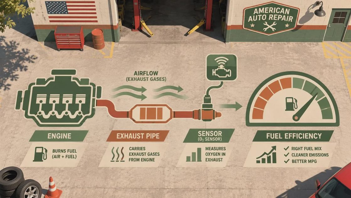
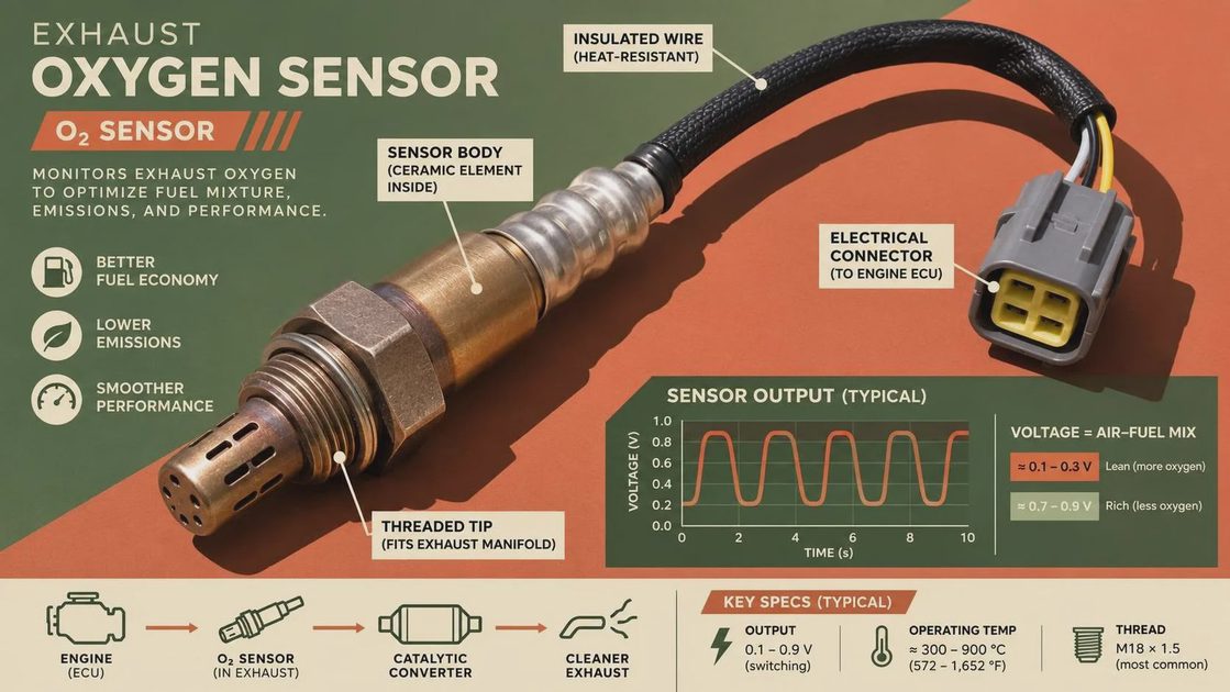
An O2 sensor measures the oxygen content in exhaust gas and reports that information to the engine control module. In a conventional narrowband design, the sensing element produces a changing voltage as the exhaust moves from oxygen-rich, or lean, to oxygen-poor, or rich. The module uses that signal to adjust injector pulse width during closed-loop operation.
A typical zirconia sensor does not directly measure fuel percentage. It compares oxygen concentration in the exhaust with oxygen in the outside reference air. Near the stoichiometric air-fuel ratio for gasoline, the voltage changes rapidly. That is why a narrowband sensor is excellent for confirming whether combustion is crossing the control point, but not for precisely measuring a broad air-fuel ratio range.
Newer vehicles often use an air-fuel ratio sensor, sometimes called a wideband sensor. It uses a control circuit and pump cell to maintain a target condition in the sensing chamber. The terminology in parts catalogs can be inconsistent, so match the replacement to the vehicle identification number, engine, connector, and emissions package rather than relying only on the phrase O2 sensor.
Reference Box: A zirconia sensing element needs a hot exhaust environment, clean reference air, and a sound electrical circuit. Silicon, coolant ash, oil ash, and sealant contamination can permanently change its response.
The heater brings the element to operating temperature quickly, allowing closed-loop control soon after startup. Heater circuits commonly operate from battery voltage through a fuse and relay, while the module monitors current or resistance. A heater code does not automatically prove the sensing element is bad; a blown fuse, damaged harness, poor ground, or water intrusion can produce the same symptom.
Symptoms and trouble codes
A failed O2 sensor can cause a check-engine light, unstable fuel trims, poor fuel economy, hesitation, or an emissions test failure. Some failures create a fixed high or low signal. Others become slow and lazy, allowing the vehicle to run acceptably while gradually increasing fuel consumption. A rough idle can be related, but it is not a specific diagnosis because vacuum leaks, ignition faults, injectors, and fuel pressure problems can create similar behavior.
Codes such as P0130 through P0167 generally point to sensor circuit, response, heater, or range concerns, but the exact meaning depends on sensor position and vehicle application. Bank 1 is the side containing cylinder one. Sensor 1 is normally upstream of the catalytic converter, while Sensor 2 is normally downstream. Always read the full code description and service information before ordering a part.
Fuel-trim data adds useful context. A positive long-term fuel trim means the module is adding fuel because it detects a lean condition. A negative value means it is reducing fuel. A false lean signal from an exhaust leak ahead of the sensor can cause the module to add fuel even when the injector and fuel pump are working correctly. That is why replacing the sensor first is often the wrong move.
If the check-engine light is flashing, treat it as a possible active misfire and avoid extended driving. Unburned fuel can overheat and damage the catalytic converter. A steady light still deserves diagnosis, especially when the vehicle has poor performance or a strong fuel odor.
How to test before replacing it
Start with a visual inspection. Look for melted insulation, harness contact with the exhaust, corrosion inside the connector, and a sensor wire stretched tight across a bracket. Inspect the exhaust manifold and pipe for cracks or soot trails. A smoke test can help locate an intake or exhaust leak that is too small to hear.
Next, scan live data with the engine fully warmed. A traditional narrowband upstream signal should switch repeatedly as the module adjusts mixture, although the exact voltage pattern varies by design. A sensor that stays fixed can be faulty, but it can also be reporting a real rich or lean condition. Compare the signal with short-term and long-term fuel trim rather than judging one voltage in isolation.
Use a digital multimeter only according to the manufacturer’s wiring diagram. Check heater resistance with the circuit disconnected and the component cool, then verify power and ground under load. Do not pierce insulation unnecessarily, and never apply battery voltage to a signal wire. A current clamp, lab scope, or scan tool graph can reveal a slow response more reliably than a basic meter.
For a wideband O2 sensor, do not expect the old rapid-switching voltage test to work. The module controls the pump cell, and scan data commonly reports equivalence ratio, lambda, or pump current. Use the factory procedure. The wrong test can lead to an expensive replacement that does not address the fault.
Oil, coolant, and fuel contamination
The sensing element is exposed to exhaust chemistry, so engine condition matters. Silicone from unapproved sealants can poison the element. Leaded fuel damages most modern emissions sensors. Excessive oil consumption can leave ash deposits, while a leaking head gasket can expose the exhaust to coolant contamination. A sensor covered in white, gray, or chalky deposits is evidence worth recording, not merely a reason to install another part.
The same principle applies to fuel system problems. A leaking injector, restricted air filter, low fuel pressure, or unmetered air can drive mixture outside the sensor’s normal operating range. The sensor may be accurately reporting a problem elsewhere. Correcting the root cause first protects the replacement and helps the fuel trims return to normal.
Do not spray cleaners, carburetor solvent, or compressed air into the sensor connector. Avoid anti-seize on the sensing tip. Some replacement sensors include the correct compound on the threads; if the instructions permit additional compound, keep it away from the first thread and element. A contaminated connector can be cleaned only with a product approved for electrical contacts and allowed to dry fully.
Choosing and installing a replacement
Use an original-equipment-style direct-fit part when possible. Direct-fit sensors preserve the correct connector, wire length, heater characteristics, and calibration. Universal splice-in parts can work in skilled hands, but a poor crimp or incorrect wire identification creates intermittent faults that are difficult to find. Never select a downstream sensor solely because it looks similar to the upstream unit.
Before removal, warm the exhaust briefly if safe, then shut the engine off and use proper gloves and eye protection. Hot exhaust components cause serious burns. Apply penetrating fluid to the bung, protect the wiring, and use the correct sensor socket. If the threads are damaged, repair the bung rather than forcing the new sensor into place.
After installation, clear codes only after recording freeze-frame data. Confirm that the heater monitor, fuel-system monitor, and oxygen-sensor monitor run successfully during the drive cycle. A cleared light is not proof of repair. Recheck for leaks, inspect live fuel trims, and verify that the replacement signal responds as expected.
The practical diagnosis
The best O2 sensor diagnosis combines code information, wiring inspection, exhaust checks, fuel-trim data, and a temperature-appropriate signal test. Parts-counter staff can explain this sequence in a few sentences: the sensor reports exhaust oxygen, but it does not cause every rich or lean condition. Technicians should prove power, ground, signal behavior, and the condition of the engine before replacing it.
If your customer asks, the one-line answer is this: an O2 sensor is a feedback device, not a tune-up part. Replace it when testing shows a failed circuit, contaminated element, or unacceptable response, then correct any oil, coolant, fuel, or exhaust problem that caused the failure. Here’s the chemistry, here’s the spec, here’s what to do with it.

No comments yet — be the first to share a thought.